Google

Tuesday, December 4, 2007

Obstacle Sensor

Sharp GP2D12 IR Range Sensor - 10cm to 80cm

Infrared rangefinder 10cm (~4") to 80cm (~30")
• Analog Interface
• Operating supply voltage is 4.5V-5.5V
• Suitable to use as a sensor for a obstacle robot

Read the distance of the object in front of your robot. The Sharp GP2D12 IR Range Sensor takes a continuous distance reading and reports the distance as an analog voltage with a distance range of 10cm (~4") to 80cm (~30"). The interface is 3-wire with power, ground and output.


Micro beam sensors EX-D200E can used to sense the object. This sensor have built-in amplifier. Selecting output operation by connecting control wire will make it dark-On or light-On. The maximum sensing range is up to 200mm.Its need 12V voltage supply.

Thursday, November 29, 2007

MicroC source code

/*Programming:Blink two LEDs
* this example smoothly blinks LEDs on RC1 and RC2 alternatvely
* using PIC CCP module configured as PWM output
*
* source code example for mikroC
* feel free to use this code at your own risks
*
* target : PIC16F877A, 8 Mhz crystal
* HS clock, no watchdog.
*
* easyPIC4 settings :
* LEDs on PORTC enabled
*
*******************************************************************************/

void main()
{
unsigned char dc ;

TRISC = 0 ; // set PORTC as output
PORTC = 0 ; // clear PORTC

/*
* configure CCP module as 4000 Hz PWM output
*/
PR2 = 0b01111100 ;
T2CON = 0b00000101 ;
CCP1CON = 0b00001100 ;
CCP2CON = 0b00111100 ;

for(;;) // forever
{
/*
* PWM resolution is 10 bits
* don't use last 2 less significant bits CCPxCON,
* so only CCPRxL have to be touched to change duty cycle
*/
for(dc = 0 ; dc < 128 ; dc++)
{
CCPR1L = dc ;
CCPR2L = 128 - dc ;
Delay_ms(10) ;
}
for(dc = 127 ; dc > 0 ; dc--)
{
CCPR1L = dc ;
CCPR2L = 128 - dc ;
Delay_ms(10) ;
}
}
}

Monday, November 19, 2007

Moving Message LCD Display System (MMDS) via SMS


The aim of this project is to design Moving Message LCD Display System (MMDS) via SMS entry using Rabbit Core Microcontroller 2000 (RCM2000) and integrate it with Global System for Mobile Communication module (GSM). This project presents an application of an LCD Display module that can display the message display when the message is sent via mobile phone. The system receives message through Short Message Service (SMS). In order to the send SMS to system, SIM card from Hotlink starter pack had been used. In conclusion, the MMDS system can replace the conventional entry method using handheld infra red remote console or keyboard.

Tuesday, November 13, 2007

Saturday, November 3, 2007

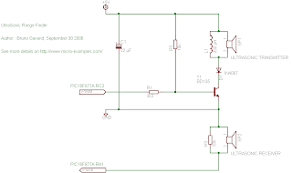
Ultrasonic Sensor

Obstacle Robot

Basically, the robot needs a micro controller to control the robot.For this robot, it used PIC 16F877A as a controller.It also used driver motor L293B to control motor forward and reverse.For this robot, micro beam sensor was used to sense the obstacle and give the input to PIC16877A.This robot will turn right when its sense the object in front. The controller should be program by C language into PIC. Other sensors that can be used such as infra-red, ultrasonic sensor, GP2D12 IR-Range, and foto-electric sensor . All this sensors also shown in this blog.You can find it..

You also can get more information at our link at http://obstaclerobot.blogspot.com.


Line following Coding Using CCS

#include <16f877.h>
#use delay(clock=20000000)
#use rs232(baud=9600, xmit=PIN_C6, rcv=PIN_C7)
#fuses HS,NOPROTECT,NOWDT,BROWNOUT,PUT,NOLVP
#define motor2 PIN_E0 //MOTOR 1
#define motor1 PIN_E1 //MOTOR 2
#define enable1 PIN_c1// enb 1
#define enable2 PIN_c2 //enb 2
main()
{
while(1)
{
if(!input(PIN_E0)&&(!input(PIN_E1)))
{
output_high(enable1);
output_high(motor1);
output_high(enable2);
output_high(motor2);
delay_ms(1000);
}
else if(input(PIN_E0)&&(!input(PIN_E1)))
{
output_high(enable1);
output_high(motor1);
output_low(enable2);
output_high(motor2);
delay_ms(1000);
}

else if(!input(PIN_E0)&&(input(PIN_E1)))
{
output_low(enable1);
output_high(motor1);
output_high(enable2);
output_high(motor2);
delay_ms(1000);
}
else
{
output_high(enable2);
output_low(motor2);
output_high(enable1);
output_low(motor1);
delay_ms(1000);
}
}

Vision Robot

What is robot vision?

The field of robot vision guidance is developing rapidly. The benefits of sophisticated vision technology include savings, improved quality, reliability, safety and productivity. Robot vision is used for part identification and navigation. Vision applications generally deal with finding a part and orienting it for robotic handling or inspection before an application is performed. Sometimes vision guided robots can replace multiple mechanical tools with a single robot station.

Robot VisionCreating Sight

A combination of vision algorithms, calibration, temperature software, and cameras provide the vision ability. Calibration of robot vision system is very application dependent. They can range from a simple guidance application to a more complex application that uses data from multiple sensors.

Algorithms are consistently improving, allowing for sophisticated detection. Many robots are now available with collision detection, allowing them to work alongside other robots without the fear of a major collision. They simply stop moving momentarily if they detect another object in their motion path.

Seeing Savings
Robotic vision makes processes simpler, more straightforward, thus cutting costs:

* Fixtures – Robot vision eliminates any need for hard tooling or fixturing. Now, products can be identified and applications performed without any need for securing.
* Labor – There are labor and machinery savings that come with robotic vision. There is no need for sorts, feeders or upstream actuators anymore. Nor is there any need for labor to load or orient parts.

Finding the Right Vision

When deciding on the right robot vision guidance, work with an integrator you can trust and consider the following:

* Communication – Robot vision must work and connect with the robot system and application. A disconnect could harm the robot or the product and cause loss of production and quality.

* Environment – The workplace must be controlled so that robot vision remains sharp. Every contributing element in the environment, including lighting, product color changes, airborne chemicals, must be considered and tested.